Vehicle Assembly – Floor Pan Build System
| By dsidsc | 0 Comments
PROJECT
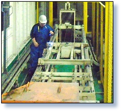
Floor Pan Build System
CUSTOMER
General Motors Corporation
Objectives
- Analyze the system and identify potential bottlenecks.
- Evaluate the systems’ throughput at 100% capacity, with allowances for probable unscheduled downtime.
- Evaluate “what-if” scenarios to improve system performance to a gross of 115 JPH.
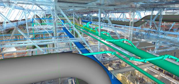
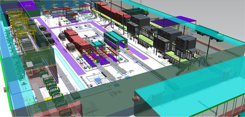
Description
Floor Pan Build System consisting of material handling and shuttle robots, welding robots, operators, turntable stations, and part sub-assemblies.
General Methodology
A baseline simulation model was developed reflecting the current operating conditions of the Floor Pan Build System. An analysis verified that the system’s operationallogic and cycle times could support the measured gross rate, taking into consideration process interaction, but without the effects of downtime. A net rate analysis was performed employing downtime data derived from actual observations. The data was analyzed, filtered and incorporated into the model when evaluating the impact of downtime on the system. Experimentation with respect to cycle time reductions was performed with the objective of achieving a target gross throughput of 115 JPH
“Bottom Line” Results
BASE MODEL:
Gross Throughput –> 99.6 JPH
Net Throughput –> 85.0 JPH
AFTER CYCLE TIME CHANGES:
Gross Throughput –> 114.6 JPH
Net Throughput –> 97.5 JPH
Recommendations on ways to reduce cycle times in “arious al8Bs went offered, and included in the final report. For example, regstrling shuttle robots 10 and 19, the suggestion was made to eliminate the shuttle robots’ staging movements, thus eliminating redundant parts handling and reducing cycle times.


 These training classes are designed to teach facility personnel the fundamentals of Conveyor Systems Engineering so they will have an understanding of each system’s overall functions and capabilities.