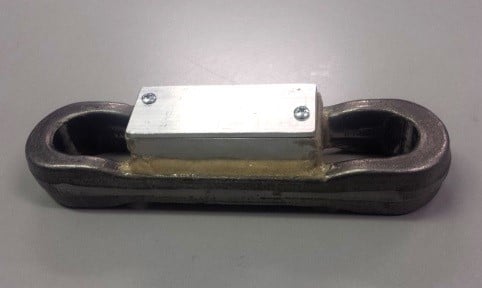
Design Systems, Inc. proudly introduces an additional offering to its growing list of Conveyor Health Assessment services. The tension of the chain can be measured through the length of the conveyor with a Strain Gauge Link.
Strain Gauge Link Benefits:
Maximum tension in chain and location of the tension
Compare real tension data to theoretical Chain Pull results to avoid adding unnecessary drives
Chain Pull at each drive for the current load condition
Rolling friction of chain to verify lubrication effectiveness
Air pressure needed at take-up to give minimum system tension
Pulsing of chain tension from engagement with the drive’s cat chain
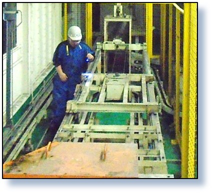
Link can be shipped, installed and removed by plant personnel, then returned for data processing, to limit engineering time in the field
Results presented on a graph of tension vs length of conveyor
Temperature limit is 170°F due to battery limitations. Higher temperature applications are possible with the data logger in an insulated enclosure attached to the chain.
Other Possible Configurations:
Drive Monitor
A Strain Gauge Link will show the difference in tension before and after it passes a drive. A drive monitor sensor will show the Chain Pull at the drive for varying load conditions that occur during the day. Results are presented on a graph of Chain Pull vs. time to determine maximum pull of the drive.
Carrier Rolling Friction
A tension sensor can be used to measure individual carrier pull by temporarily attaching to the preceding carrier. This will give actual rolling friction for the carrier wheels to use in Chain Pull analysis, instead of a theoretical value.
Custom Installations
Strain Gauges can also be added to the framework of a conveyor turn that is at the lowest tension in the system. When the loads vary, the take-up air pressure can be adjusted with feedback from the gauges to keep chain at the lowest tension which reduces wear.
Have a conveyor system but not sure you are fully utilizing its functionality? Maintenance issues causing unexpected costs, personnel time and downtime? Design Systems, Inc. has been providing Conveyor Engineering Services for our customer’s material handling needs since 1983. As an engineering service provider and not an equipment supplier, we are a completely unbiased engineering resource whose only goal is to design the best possible solution for our client’s unique circumstances.
Let us help you get the most out of your conveyor systems; understand its capabilities, maintenance requirements and design parameters. Classes offered by Design Systems experienced team of engineers can be tailored to your specific conveyor systems and will typically run from a 1-day overview session to a more in-depth week long class.
Save Maintenance Costs – Do it yourself
These training classes are designed to teach facility personnel the fundamentals of Conveyor Systems Engineering so they will have an understanding of each system’s overall functions and capabilities.
This systems-oriented course is ideal for cross-training plant personnel. People who will benefit from attending this course include:
Plant and Facility Engineers
Supervisors
Building Engineers
Safety Directors
Environmental Health and Safety Personnel
Conveyor Systems Included in the Course Overview
Overhead Power and Free
Inverted Power and Free
Skillet System
Chain-On-Edge System
Skid System
Flattop System
Power Roll and Belt Systems
Basic Transfer Methods
Topics Covered for Each System
Chain Pull Calculations
Throughput Analysis
Horsepower and Drive calculations
Take-up Calculations
Clearance Studies (Horizontal and Vertical)
Min / Max / Float Calculations
Zone Counts
Strip Out Bank Calculations
JPH Calculations
Basic Carrier Designs and Carrier Quantity Analysis
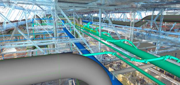
Design Systems, Inc. uses a broad suite of 3-D design software, including, to name a few, CATIA, Unigraphics, Solid Edge, AutoCAD, FactoryCad. Visualization and animation software include: UGS Teamcenter Visualization Quality and 3-D Studio Max.
Facility Layout Development
Design Systems, Inc. applies its 25 years of experience with facility and material handling engineering to the development of comprehensive 3-D plant layouts.
Native 3-D drawings conversions
2-D to 3-D drawings
Field check to 3-D drawings
Laser Scanning to 3-D drawings
3-D to AVI “Fly throughs” Development of 3-D concept and Bid Package level layouts for facilities and conveyor systems.
Development of material handling and material display layouts.
Layout support using “Smart Object”
Work Cells/ Workstations
From the 3-D layout model, any workstation or cell can be isolated allowing:
Identification and study of the workstation and it’s environment, including carriers, racks, tools, rails, etc.
Analysis of operator workflow and packaged materials within the work cell.
Confirmation of work elements required within the workstation.
Review and analysis of ergonomic issues.
Uses of 3-D Layout Design
Exceptional presentation tool
Interference Detection
Coordination, and validation of tooling design / location
s a core competency, Design Systems, Inc.has extensive “hands-on” experience with 3-D carrier design and virtual modeling.
CATIA V4 & V5 and Unigraphics software are used for the design of carriers and fork transfers. These design tools provide customers with better and more accurate detail design, thus reducing the number of prototype carriers required for testing and design proofs.
Using Finite Element Analysis (FEA) software with the 3-D models, Design Systems can “Right Size :” the structural elements of the carriers for both static and dynamic loading. This eliminates “Over Sizing” of carrier members which reduces cost in carrier fabrication, conveyor drive HP requirements and conveyor system wear.
Our expertise with 3-D software and “big screen” conferencing facilitates highly effective coordination with the client and suppliers. It also reduces carrier design time allowing best possible communications regarding design intent and decision -making.
Design Systems has the ability to connect with our customers via:
T1 Lines
Virtual Product Manager (VPM)
AutoWeb CCX-I Mailbox
AutoWeb GCX-I Mailbox
“BOTTOM-LINE” RESULTS:
COST SAVINGS:
“Right Sizing” carrier structures.
Design carriers accurately the first time.
Multiple product capability using product math data.
Early design to allow coordination with suppliers.
Early design allows prototype build at customer facility.

 These training classes are designed to teach facility personnel the fundamentals of Conveyor Systems Engineering so they will have an understanding of each system’s overall functions and capabilities.