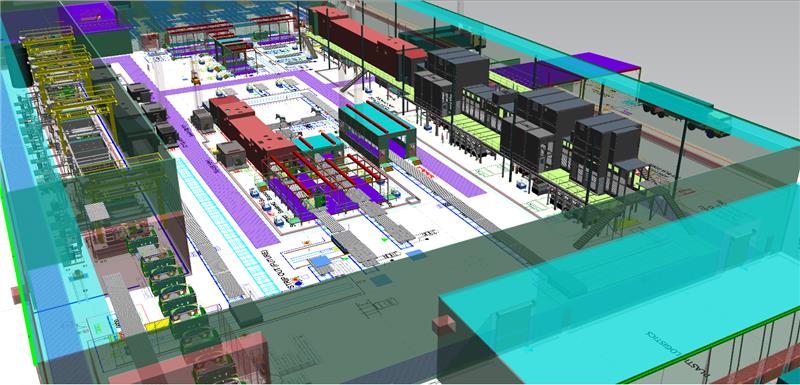
Vehicle Assembly – Underbody Robotic Sub-Assembly

   |   By  |  0 Comments

Vehicle Assembly Simulation

PROJECT

Underbody Robotic Sub-assembly

CUSTOMER

General Motors Corporation

Objectives

  1. Evaluate and prove the systems’ ability to meet throughput objectives of 90 JPH “gross” and 77 JPH “average yield.”
  2. Identify any deficiencies (bottlenecks) in cell flow as well as potential improvements to the cell design.
  3. Define the effects of downtime, part shortages and operator efficiency.

Description

A base model was developed for each of the subassembly cells under study. The base model simulation was run without the effects of downtime to verify that objective #1 was achieved and that input parameters were correct. Based on a random approach, downtime effects were applied to the model, and changes in the system behavior were recorded. This allowed the identification of system bottlenecks from statistical data. “What-if” scenarios were then performed on the simulation model to determine how the effects of downtime, material shortages and operator overcycles can be offset, thereby improving throughput.

“Bottom Line” Results

System Throughput: 78.5 JPH Base model
Downtime Applied: 73.9 JPH
Early and Late Breaks: 64.9 JPH
Part Shortages On: 59.3 JPH
Quality Issues On: 47.4 JPH


Station 13 identified as the system bottleneck. Part 14957 shortage significantly affected throughput.

Eliminating material shortages associated with part 14957 –> resulted in 52.1 JPH


Replacing Station 13 fixed conveyor with an accumulating conveyor –> resulted in 52.8 JPH


Improving Station 13 and Robot 11 cycle time to 40 sec –> resulted in 59.5 JPH


Eliminating early and late breaks –> resulted In (;1.4 JPH


Eliminating quality issue problems and resulting delays –> resulted in 84.2 JPH

Vehicle Assembly – Floor Pan Build System

   |   By  |  0 Comments

Mechanic engineer holding a digital tablet with engineering research software application on the screen, aerodynamic test of parameters data in the wind tunnel of an eco-friendly car body

PROJECT

Floor Pan Build System

CUSTOMER

General Motors Corporation

Objectives

  1. Analyze the system and identify potential bottlenecks.
  2. Evaluate the systems’ throughput at 100% capacity, with allowances for probable unscheduled downtime.
  3. Evaluate “what-if” scenarios to improve system performance to a gross of 115 JPH.

Description

Floor Pan Build System consisting of material handling and shuttle robots, welding robots, operators, turntable stations, and part sub-assemblies.

General Methodology

A baseline simulation model was developed reflecting the current operating conditions of the Floor Pan Build System. An analysis verified that the system’s operationallogic and cycle times could support the measured gross rate, taking into consideration process interaction, but without the effects of downtime. A net rate analysis was performed employing downtime data derived from actual observations. The data was analyzed, filtered and incorporated into the model when evaluating the impact of downtime on the system. Experimentation with respect to cycle time reductions was performed with the objective of achieving a target gross throughput of 115 JPH

“Bottom Line” Results

BASE MODEL:

Gross Throughput –> 99.6 JPH
Net Throughput –> 85.0 JPH


AFTER CYCLE TIME CHANGES:

Gross Throughput –> 114.6 JPH
Net Throughput –> 97.5 JPH


Recommendations on ways to reduce cycle times in “arious al8Bs went offered, and included in the final report. For example, regstrling shuttle robots 10 and 19, the suggestion was made to eliminate the shuttle robots’ staging movements, thus eliminating redundant parts handling and reducing cycle times.

Material Handling Systems – Preform AGV Delivery System

   |   By  |  0 Comments

Automated Guided Vehicles

PROJECT

PreformAGV Delivery System

CUSTOMER

Western Container Corporation/Coca Cola

Objectives

  1. Evaluate and test the AGV systems’ throughput capability under anticipated operating conditions.
  2. Verify that eight AGVs will maintain throughput demands.
  3. Compare the effects of one, two or three home stations (AGV park empty waiting for next pick-up task).

Description

Automated Guided Vehicle (AGV) pick-up from 12 additional preform machines and delivery to automated bin unload station.

“Bottom Line” Results

AGY system can service 24 preform machines without ever impacting preform machine throughput (blocked by full containers).

One home station (empty AGY parking) provides the greatest flexibility and quickest response time to waiting machines.

System would meet production requirements with as little as five AGYs, indicating excess system capacity.

Material Handling – Large Package Sorting System

   |   By  |  0 Comments

Package sorting system

PROJECT

Large Package Sorting System

CUSTOMER

United States Postal Service

Like all USPS processing plants, a Bulk Mail Center (BMC) must use its resources wisely to meet the challenges of a changing mail processing environment.

Presently, package piece count is increasing 20 to 70% annually, prompting the BMCs to request installation of a Large Package Sorting System (LPSS). Without these systems, package volume will overwhelm BMCs in the near future, causing a degradation in service and higher costs due to an increase in manual processing.

The LPSS operates within BMCs and other USPS mail processing facilities to sort large parcels. Systems include a sorter and equipment to deliver and take away product from the sorter. The configuration of the system is site-specific depending on the space availability, package count, and number of distributions required.

These are the important points relative to the LPSS project.

Flexible Model for Evaluating LPSS Systems

The simulation was constructed with distinct modules, such
as singulator, scanner, etc., so that different configurations
could be easily modeled.

If different configurations are modeled, floor space requirements may be more accurately quantified after determining the effectiveness of the new system.

Package Sort Plans

The simulation model was tested using one sort plan. To optimize the number of runouts, changes must be made to the sort plan and the staffing of the runouts. Alternatives include:

  • Combining low volume runouts and having multiple pallets at one runout.
  • Splitting up high volume runouts to ease workload and minimize “full” conditions.
  • Using multiple operators at single high volume runouts.

Overall

The highest impacting deficiency in the LPSS system today is the sweep operation at the end of the runouts.

The uneven distribution of packages to these runouts decreases sweeper utilization and increases packages sent to the mis-sent runout, which is less efficient than the regular runouts. Optimizing the sort scheme will correct a large part of this problem.

Material Handling – Finished Paper Roll Handling System

   |   By  |  0 Comments

Paper Roll Handling System

PROJECT

Finished Paper Roll Handling System

CUSTOMER

Appleton Papers, Inc.

Objectives

  • Evaluate and prove the AEM system’s ability to meet the design throughput requirement of 5100 rolls per day.
  • Identify any deficiencies (bottlenecks) in the system flow and determine potential design improvements.
  • Assist with controls development, including flow logic and AEM path zoning to insure design throughput objective is reached.
  • Evaluate each order sortation area’s ability to meet the design throughput requirement.

Description

System 1: Automated Electrified Monorail (AEM) delivery of cut paper rolls from nine rewinders to seven wrapping machines.

System 2: AEM delivery of wrapped paper rolls from seven wrapping machines to four order sortation areas.

System 3: Palletized order sortation using semiautomated bridge cranes.

“Bottom Line” Results

System can achieve 5100 rolls per day requirement Detennined optimum dispatch locations for empty AEM vehicles. Developed dispatch algorithm for empty vehicle selection of rewinder pick-up location. Developed AEM path flow logic to minimize vehicle flow restrictions through the following methods:

  • AEM track zoning
  • Vehicle priorities
  • Pick-up/Drop-off decision logic

Determined minimum vehicle requirements of 12 for system ‘1 and 15 for system 12. Vehicle costs were $80,000 and $30,000 for systems ‘1 and 12, respectively.

Simulation Engineering

   |   By  |  0 Comments

Simulation Engineering

Do It Right The First Time

Design Systems, Inc.’s simulation engineering experience spans more than 20 years and cumulative staff experience more than 100 years. The process involvement over these years has been in a multitude of industries.

The most critical component of simulation engineering analysis is the ability to understand the dynamics of a system and then translate that understanding into a simulation model that will accurately reflect the system(s) and its dynamic interactions. This analysis allows your project goals to be quickly and accurately validated.